
Photo chemical machining vs laser cutting comes up most often when an engineer has a thin sheet-metal part with fine features and is weighing speed of laser against the burr-free, stress-free finish of etching. Stamping enters the conversation at higher volumes, when tooling cost can be amortised. The right choice depends on geometry, material thickness, tolerance, and how many parts are needed. This article walks through where each process wins and where it doesn’t.
What each process does, briefly
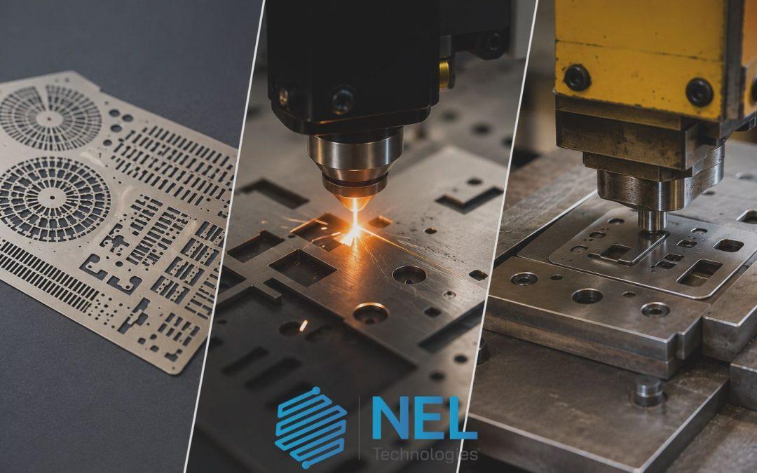
Photo chemical machining (PCM), also called chemical etching or photochemical etching, removes metal with a controlled chemical etchant. A photoresist mask defines the geometry, the etchant dissolves the exposed metal, and the part comes out with no mechanical or thermal stress. Our chemical etching explainer covers the full process step by step.
Laser cutting uses a focused beam to vaporise or melt metal along a programmed path. It’s fast, single-piece, and well suited to mid-thickness sheet.
Stamping shears or forms metal with a hard tool. Once the tool is built, parts come off the press at high speed and low unit cost.
Three processes, three economic profiles, three different sweet spots.
When PCM beats laser cutting
The cleanest comparison is on thin sheet with intricate features. Industry guidance commonly cites PCM as a strong fit up to around 2.5 mm, with the relationship between feature size and material thickness driving what’s achievable.
PCM has the edge when:
- Edges must be burr-free and stress-free. PCM doesn’t shear or melt the metal, so there’s no recast layer, heat-affected zone, or burr. Laser leaves a thin recast that often needs secondary cleaning, and edges can show heat colouring.
- Magnetic or electrical properties must be preserved. Heat from laser cutting can alter the magnetic permeability of mu-metal, electrical steel, and similar grades. Etching leaves the substrate’s properties unchanged.
- The part has many small, complex features. Laser cuts each feature in sequence, so cycle time scales with complexity. PCM etches the entire sheet at once, so a 200-feature part takes the same time as a 20-feature part.
- Sheet thickness is below about 0.5 mm. Below that range, laser kerf, edge quality, and handling become harder to control. PCM is comfortable down to 25 µm foil.
Laser keeps the edge for one-off prototypes in mid-gauge sheet, very thick material, or where lead time on a photo-tool would slow things down (though most PCM tooling is fast and inexpensive compared with hard tooling).
When PCM beats stamping
Stamping is hard to beat on cost-per-part once the tool exists and the volume justifies it. The question is whether you ever reach that volume, and whether the part can survive the press.
PCM is the better choice when:
- Volumes are low to medium, or uncertain. Hard tooling is a fixed cost. PCM uses a photo-tool that’s relatively cheap and quick to update, which means design changes don’t restart the tooling clock.
- The design is still iterating. A revision to a stamped part means a tool modification or a new tool. A revision to an etched part means a new artwork file.
- Features are too fine, or too close to edges, for stamping. Sheared edges need clearance from features. Etched parts don’t.
- The material can’t take press forces. Thin foils, brittle alloys, and parts where work-hardening matters are cleaner to etch than to stamp.
For very high volumes of simple geometry in mid-gauge sheet, stamping wins on unit economics. PCM rarely competes at those volumes on cost alone, but it competes on flexibility, lead time, and feature fidelity.
Tolerances and what’s realistic
Tolerance in PCM is driven by the relationship between feature size and material thickness, and by process control across resist, exposure, etchant chemistry, and handling. As a working rule, feature widths shouldn’t go significantly smaller than material thickness if you want clean definition. Within that envelope, PCM holds tight, repeatable tolerances suitable for shims, lead frames, EMI shielding, encoder discs, and precision filters.
Laser tolerances depend on focus, beam quality, and material. Stamping tolerances depend on tool wear and press setup. Each has its window. The point isn’t that one is universally tighter than the others, but that the windows differ, and the fit to the part matters more than the headline number.
Materials and finish
PCM works with most precision engineering metals: stainless grades 304, 316, and 301 in spring temper; brass; phosphor bronze; beryllium copper; copper; aluminium; and specialist alloys including Inconel, Monel, mu-metal, Invar, and Kovar. Our photo etching materials guide covers what each grade brings and where the limits sit.
Surface finish from PCM is matte, uniform across the part, and free of burr or recast. Laser leaves an oxide edge in many materials. Stamping can leave a bright, sheared edge with a small burr that’s straightforward to deburr but isn’t free.
Choosing between them: a practical view
The decision tends to follow this pattern in real projects:
- Thin sheet, complex features, low to medium volume → PCM is usually the right call.
- Mid-gauge sheet, simple geometry, prototype or low volume → laser often makes sense.
- Mid-gauge sheet, simple geometry, high volume → stamping wins on cost.
- Thin foil, fine features, any volume → PCM, almost always.
- Magnetic, electrical, or temperature-sensitive materials → PCM, to preserve substrate properties.
For projects that don’t fit cleanly into one box, the answer often comes from a feasibility conversation rather than a spec sheet. Our guide on choosing a PCM supplier covers the questions worth asking before committing.
Bringing it together
Photo chemical machining isn’t a replacement for laser or stamping. It’s the right answer in a defined envelope, and the wrong answer outside it. The envelope is thin to mid-thickness sheet, fine or complex features, low to medium volumes, and applications where edge quality or substrate integrity matters.
If you have a part where that profile fits, share your CAD file and material specification with our PCM team and we’ll come back with a feasibility view and an honest comparison if another process would serve you better.